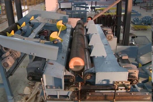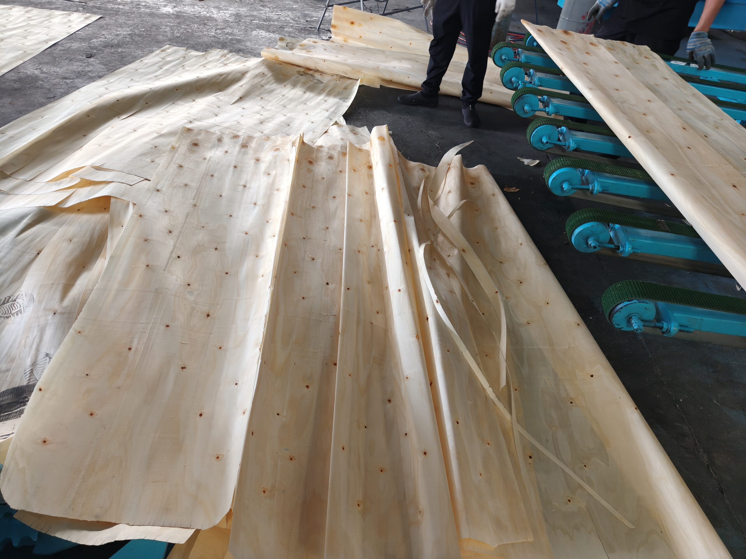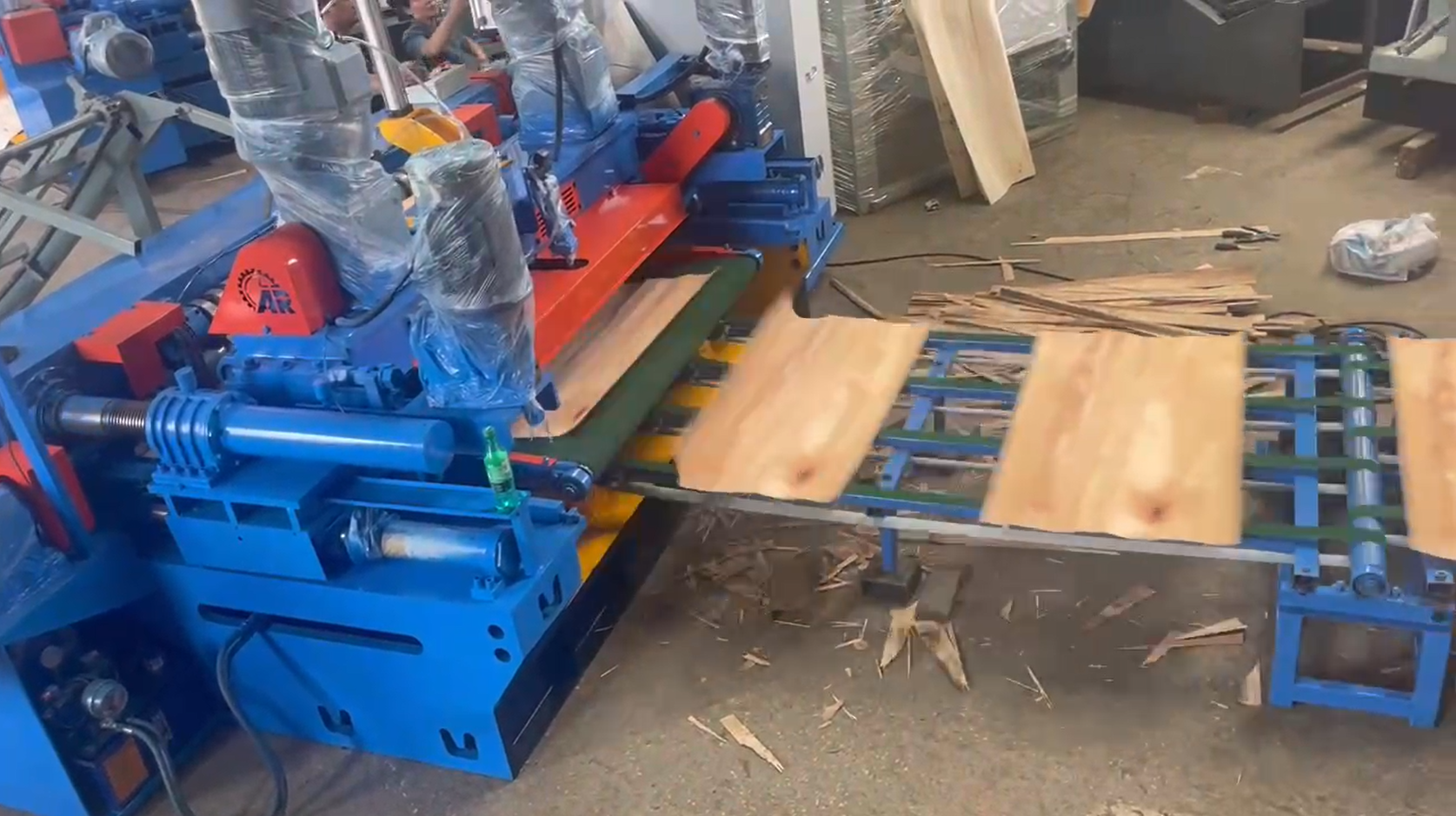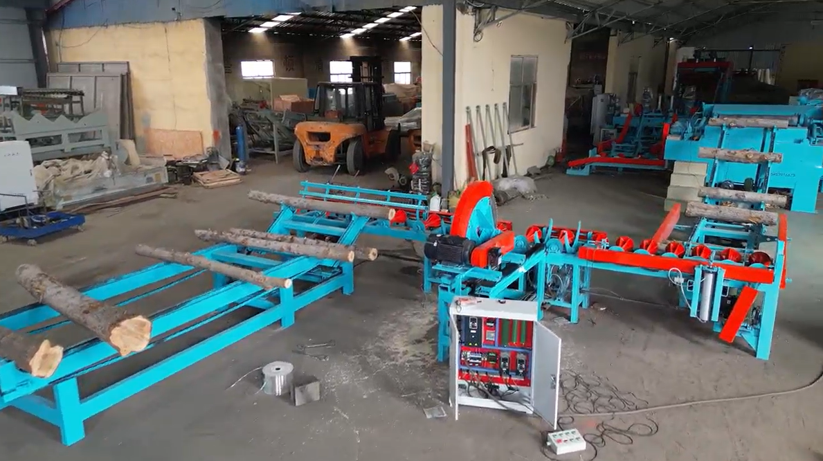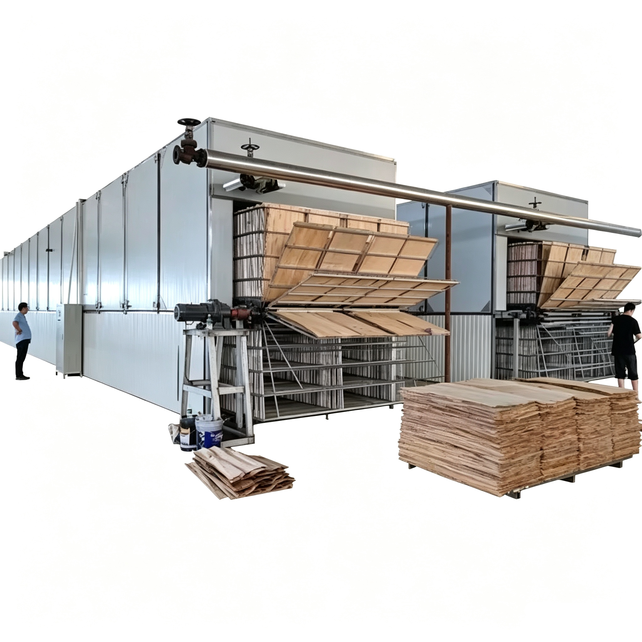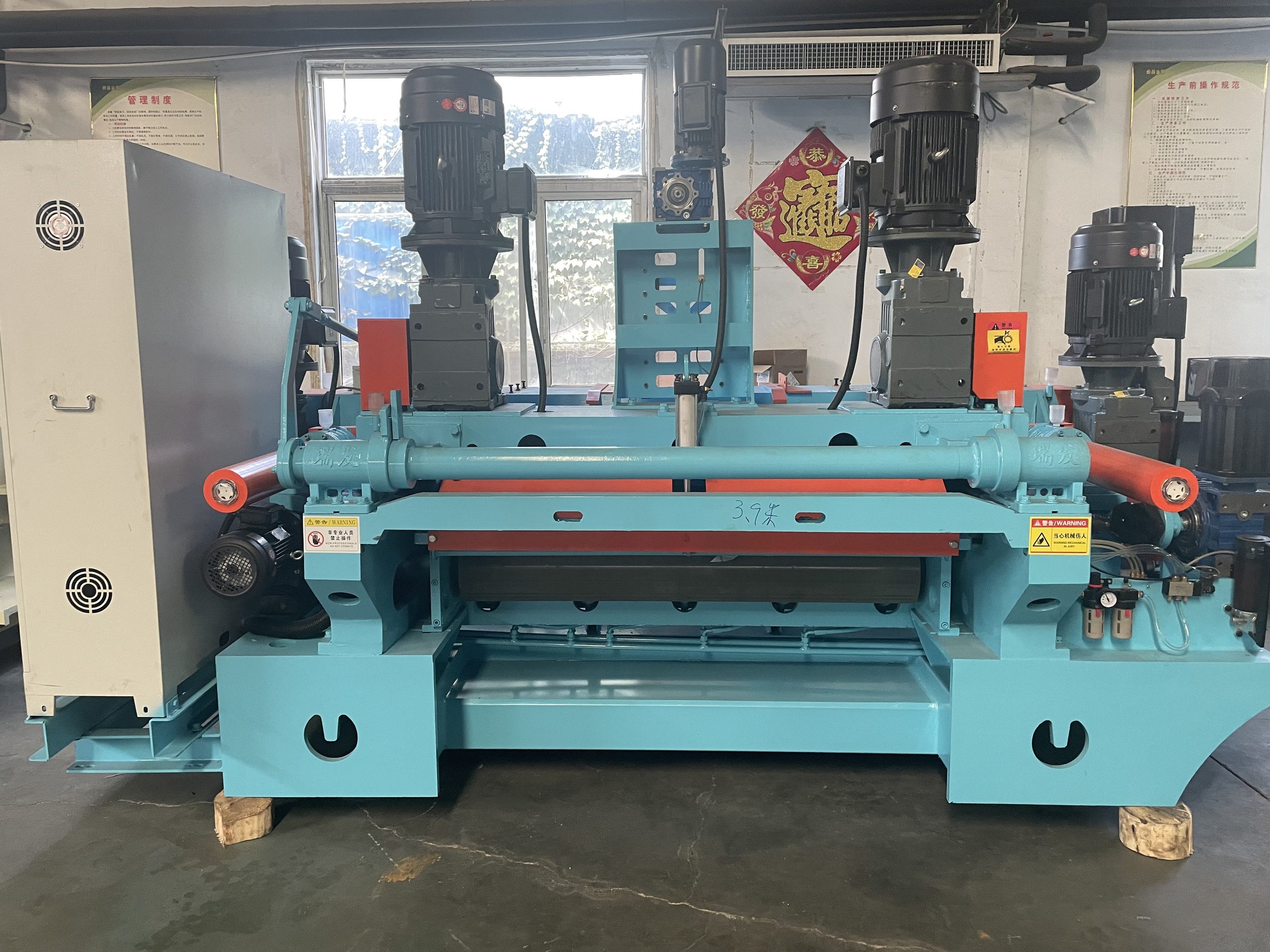

The bed and frame system of a rotary lathe is the fundamental load-bearing structure of the entire machine, acting as the “skeleton” of the equipment. The rigidity, vibration damping performance, and geometric accuracy of the machine bed directly determine the veneer thickness uniformity, surface flatness, presence of waves, bulges, and cracks.It is also one of the most important structural factors distinguishing high-end precision rotary lathes from ordinary economical machines.
Five Core Functions of the Bed and Frame System
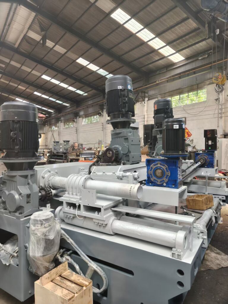
1. Load Bearing:The weight of the entire machine; Log clamping force; Continuous cutting forces; Pressure from the pressure rollers; Loads generated by the feeding system.
2. Precision Reference Base:The machine bed provides high-precision mounting surfaces and guide rail reference points to ensure:Accurate alignment of the spindle centerline; Stable movement trajectory of the knife carriage; Parallelism between the pressure roller axis and the cutting system.
3. Vibration Reduction and Absorption:Rotary peeling is an intermittent cutting process. During operation:The log diameter continuously decreases; Wood hardness varies; Cutting impacts and vibrations are generated. A rigid bed structure absorbs and reduces vibration transmission, preventing periodic waves from appearing on the veneer surface.
4. Geometric Stability:A high-quality bed maintains long-term accuracy during continuous production.It prevents:Twisting deformation; Creep deformation; Loss of machining precision over time.
5. Installation Foundation:Foundation bolt holes; Leveling structures; Safety protection mounting positions; Hydraulic pipe and cable routing channels.
I. Main Structure of the Rotary Lathe Bed
1. Main Frame Structure
High-strength steel plate welded structure;
Integrated casting structure (commonly used for large-scale equipment).
2. Guide Rail System
The guide rails are installed on the machine bed and serve as the foundation for the movement of the knife carriage and feeding mechanisms.
Common types:
Conventional sliding guide rails;
Precision linear guide rails.
3. Machine Bed Base
II.Rotary Lathe Frame and Its Functions
1. Left and Right Side Frames
The left and right frames are used for installing:
Log clamping devices;
Double roller drive system;
Bearing assemblies;
Hydraulic feeding mechanisms.
2. Crossbeam Structure
The crossbeam connects the left and right frames, improving the overall stability of the machine.
Functions:
Prevents deformation of the frame under stress;
Keeps the left and right structures synchronized;
Enhances the torsional resistance of the equipment.
3. Reinforcement Rib Design
High-quality rotary lathe frames usually adopt a reinforced rib structure.
Functions:
Increases the strength of the welded structure;
Improves impact resistance;
Prevents fatigue deformation during long-term operation.
III. Load Characteristics and Design Principles
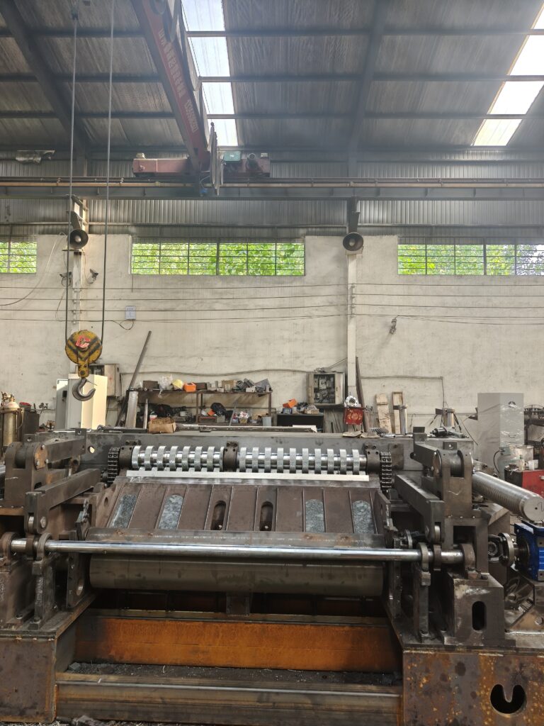
The rotary lathe is subjected to dynamic alternating loads, which are different from those of ordinary lathes:
1.The cutting force continuously changes with the diameter of the log (from large-diameter peeling gradually down to the wood core);
2.Wood contains knots, hard cores, and uneven moisture content, resulting in significant instantaneous impact loads;
3.During continuous 24-hour production, the structure is subjected to long-term alternating stress.
Key Design Principles
1. Rigidity Takes Priority Over Lightweight Design
A rotary lathe should not be excessively reduced in weight. Generally, the heavier the machine, the stronger its vibration resistance.For machines of the same specifications, cast machine beds are usually 20%–40% heavier than welded structures.
2. Closed Frame Structure
A closed-frame design should be adopted whenever possible, while avoiding single-side cantilever structures.
3. Stress Relief Treatment Is Essential
After rough machining of the machine frame, aging treatment must be carried out to release internal stress. This is a process often omitted by low-cost equipment manufacturers to reduce costs.
4. One-Time Clamping Precision Machining of Reference Surfaces
The machine bed guide rails and box joint surfaces should preferably be machined in one setup using a gantry milling machine to reduce accumulated assembly errors.
5. Reserve Space for Vibration Reduction
For large-scale equipment, a concrete foundation is recommended to provide secondary vibration damping and improve operating stability.
IV. Detailed Comparison: Cast Machine Bed vs Welded Machine Bed
| Comparison Item | HT300 Cast Iron Machine Bed | Thick Steel Plate Welded Machine Bed |
| Vibration Damping Performance | Excellent, effectively suppresses cutting vibration | Poorer, more likely to cause veneer surface ripples |
| Long-Term Precision Stability | High, with minimal deformation | Risk of gradual deformation (when internal stress is not fully released) |
| Thermal Stability | Small deformation under temperature changes | Large temperature differences may cause distortion |
| Adaptability to Impact Loads | Good | Weld seams may suffer fatigue cracking under long-term impact |
| Manufacturing Cost | Higher (advantages in mass production) | Lower, suitable for small-batch and customized machines |
| Application Scenarios | High-precision production lines for CNC thin veneer and face veneer | Thick-core plywood production lines and low-end rough peeling applications |
| Peso de la máquina | Heavier | Relatively lighter |
V.Common Faults
In most on-site veneer quality problems, the root cause is not the cutting tools or servo systems, but insufficient machine bed rigidity:
1. Periodic thickness variation and transverse ripples on veneer.Insufficient machine bed rigidity causes cutting vibration, resulting in uneven veneer thickness and surface waves.
2. Thickness accuracy becomes unstable after the machine runs for a period of time, and temporary recovery occurs after recalibration.Internal stress in the machine bed is gradually released, causing deformation of the reference surfaces and affecting accuracy.
3. Large-diameter logs peel normally, but small-core veneer shows rough surfaces and cracks.The two sides of the frame deform outward under tension, causing the knife gap to shift and become unstable.
4. Rapid guide rail wear and abnormal screw noise.Poor flatness of the machine bed causes uneven load distribution on the guide rails, leading to accelerated wear and abnormal operation.
5. Oil leakage at box joint surfaces and frequent bolt loosening after long-term use.Alternating deformation of the machine body reduces the preload force of connections, causing sealing problems and loose fasteners.
VI.Installation and Maintenance Guidelines
1. Foundation Requirements:
Heavy-duty rotary lathes must be installed on an independent concrete foundation. Direct placement on ordinary factory floors is not recommended. After leveling, the anchor bolts must be securely tightened.
2. Avoid Impacting the Machine Bed:
Impacts from log lifting operations or falling waste materials may cause permanent local deformation of the machine bed.
3. Regularly Check Connection Bolts:
The fixing bolts of the log clamping box, crossbeam, and knife carriage guide rails should be inspected regularly, as vibration environments can easily cause loosening.
4. Keep Guide Rails Clean and Properly Lubricated:
Wood chips and sand particles entering the guide rails can quickly wear the precision reference surfaces and reduce accuracy.
5. Recheck Levelness and Parallelism After Relocation:
After moving the equipment, the machine level and parallelism must be inspected and adjusted again, as displacement of the rigid structure can affect machining accuracy.
If you have any questions, please contact Peter.
Email: peterbmachines@outlook.com
WhatsApp: +86 19560831433